Beijing Dingtek Technology Corp.,Ltd
- Model No.: F500 Ultrasonic sensor
- Packaging: Ultrasonic sensor standard package
- Delivery Time: 3 Days
- Place of Origin: Beijing, China (Mainland)
- Brand: Navipro Ultrasonic sensor

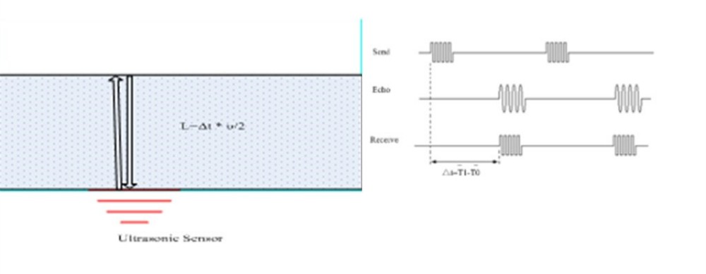
Measurement Range | 50~ 1000mm |
Blind Area | 50mm |
Resolution | 1mm or 0.1%FS, the bigger one |
Accuracy | 3mm or 0.3%FS, the bigger one (for stable container) |
Power Supply | 9-36V DC |
Current | 70mA@12VDC |
Output Signal | RS485, RS232, 0-5V, wireless (optional) |
Protocol | Dingtek /Customized |
Operating Temperature | -20~70℃ |
Storage Temperature | -40 ~ 85℃ |
Media | liquid |
Protection Rank | IP66 for transducer, IP65 for the controller box |
Mounting | Surface stick by glue or tape |
LED Display | Optional for installation |
Wireless | Optional for zigbee, wifi, GPRS, UMTS. |
Dimension | Transducer ø30, Controller box 82*55*25mm |
 4 Test Report 4.1 Device DF500, zigbee module, water bucket
 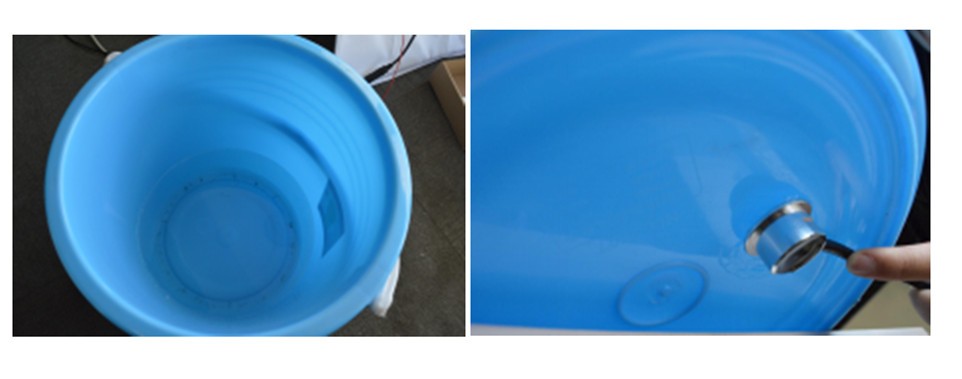 4.2 Data
 Ideal Data | Data 1 | Date 2 |
850 | 847 | 849 |
750 | 751 | 752 |
650 | 649 | 647 |
550 | 550 | 551 |
450 | 451 | 448 |
350 | 352 | 351 |
250 | 248 | 247 |
150 | 152 | 149 |
 5.1 RS232 version
 Wire | Function | Remark |
Red | Power+ | 9~36VDC |
Black (Thick) | GND | Power GND |
Yellow | TXD | RS232 Tx |
Blue | RXD | RS232 Rx |
Green | Analog | Analog output |
Black (Thin) | GND | Signal GND |
Wire | Function | Remark |
Red | Power+ | 9~36VDC |
Black (Thick) | GND | Power GND |
Yellow | B | RS485 B |
Blue | A | RS485 A |
Green | Analog | Analog output |
Black (Thin) | GND | Signal GND |
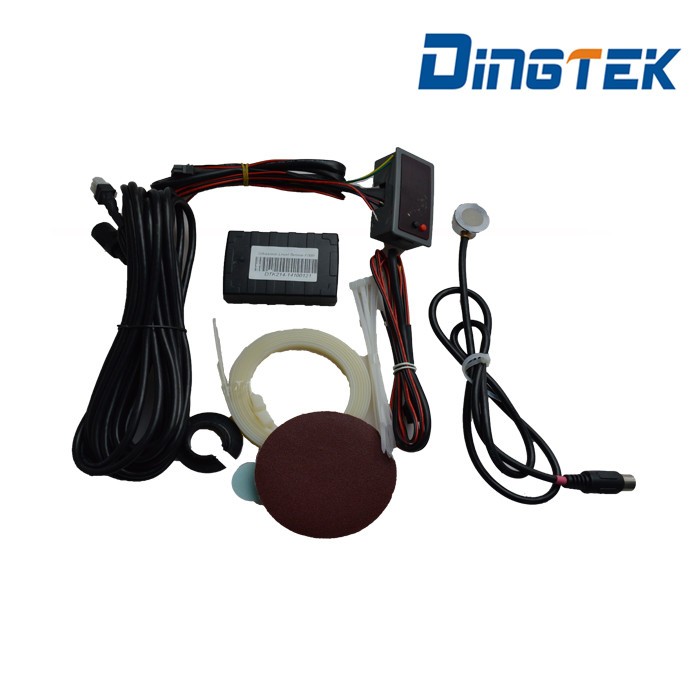
Part List | |||
NO. | Item | Quantity | Remark |
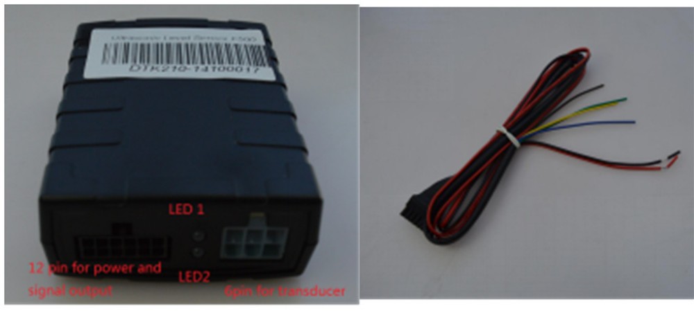
1 | Controller Box | 1 | Drive ultrasonic transducer and output signal |
2 | Ultrasonic Transducer | 1 | Transducer attached to bottom of container |
3 | Transducer Extended Wire | 1 | 7 meters |
4 | Power and Signal Cable | 1 | Power supply and signal output |
5 | Transducer Protection | 1 | Protect transducer, not necessary |
6 | Double Faced Tape | 1 | For aluminium alloy , plastic container |
7 | Tie | 1 | Fasten transducer and cable |
8 | Abrasive Paper | 1 | Clean the coating of installation point |
9 * | Couplant (vaseline) | 1 | Put between the transducer and container While finding the installation point |
10 * | Glue | 1 | Put between transducer and container for real installation after installation point found. Applicable for aluminium alloy, steel, plastic tank. Recommend loctite 380 glue. |
 : The couplant and glue is forbidden to delivery for airplane shipping or express shipping. So we do not offer them in the standard package. Please purchase at local market. The couplant (vaseline) is easy to find at medical store. It is applicable only if the glue can work for your container and the transducer.
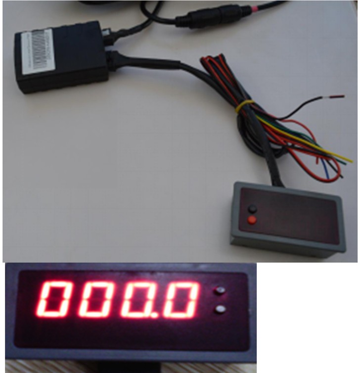
 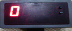 The LED Display tool is helpful to find the good installation point during installation. It is not included in standard package. One led tool is enough for multiple DF550 installation. 7 Installation & Calibration After installation, the user should input the total height, tank type and other parameter in order that the sensor can calculate the liquid height, volume and etc. 7.1 Preparation & Cleaning Before installation, please make sure the tank is stable. If you want to install for vehicle tank, please make sure the vehicle power off and stop at flat ground. Otherwise, it will result in not accurate level value. For good result of installation, it is recommended to keep the liquid more than 5cm height. Because the sensor blind area is 5cm.
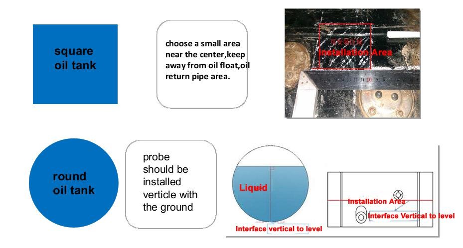
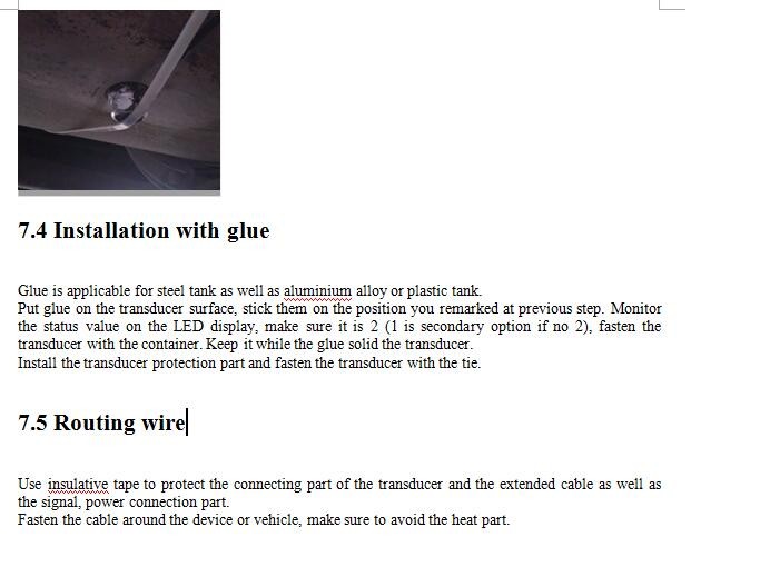
Select one flat area on bottom of the container,clean the dirt on the flat area to make it smooth. If paint cover on the steel tank, please us the abrasive paper to remove the paint cover. After cleaning, there is no any part between the transducer and the bottom shell of the container. 7.2 Finding Installation Position Connect the LED display tool with the controller box as well as the transducer. Power on it. At the beginning, the LED display tool will show the level value in cm in one screen.
 Press the two button at the same time for more than 3 seconds, it will come into the installation mode. In this mode, there are two screens. One is the level value in cm. The other is the signal status. For the signal status, it is 0-2. 2 is the best status, you can directly use this position for the final installation point. 1 is the secondary option when you can not find the signal status of 2 on this container. 0 is bad point to install, do not recommend to install on point with status 0. 7.3 Installation with double faced tape If it is aluminium alloy or plastic tank, please use the double faced tape to install.
 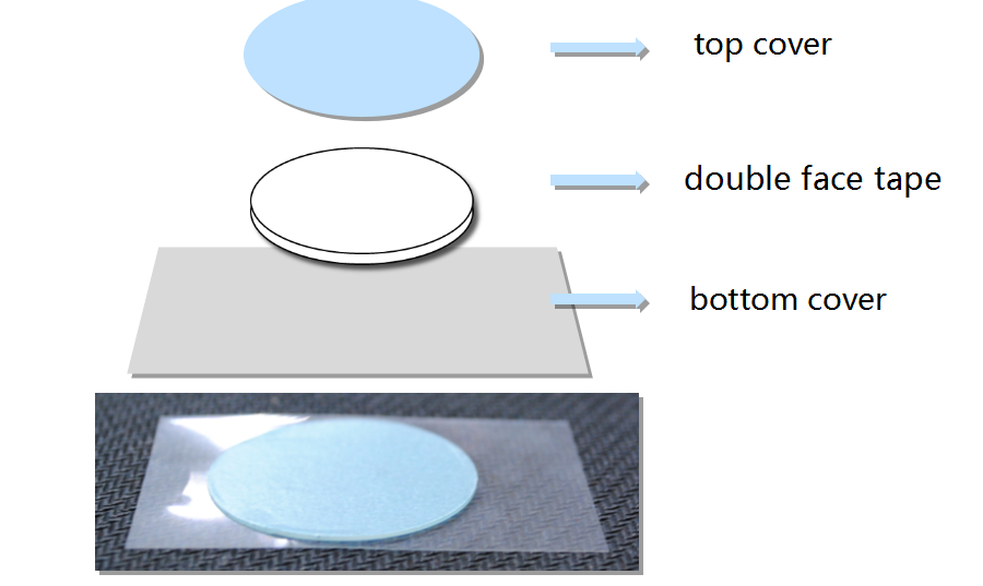 If the temperature is lower than 20℃, please warm the double faced tape firstly.
  Remove the top cover, and stick it on the transducer. While stick, please start from one side and then move forward. Do not leave air between the tape and the transducer (the aluminium alloy shell fo the transducer is not included). If there is air between the transducer and the tape, it maybe result in wrong level or not level.
 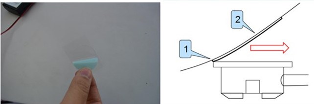 Remove the bottom cover of the double faced tape, and put it on the area you remarked on previous step. Monitor the status value on the LED display, make sure it is 2 (1 is secondary option if no 2), then fasten the transducer by the tape with the container bottom. Keep more than 1 minutes.
 Certifications
- Business Type : Trade Company
- Product/Service : liquid level sensor , GPS tracker , Temperature sensor
- Tel : 13910707690